Plain Gauges,
Limits and Fits
Plain gauges generally fall into two types:- plugs for internal holes and rings or gaps, sometimes referred to as ‘snap’ or caliper gauges for shafts.
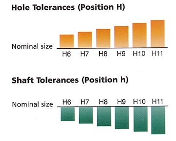
The tolerance and position of a hole or shaft is described by a letter and a number. A capital letter denotes a hole and a small letter a shaft. The letter describes the position of the component tolerance relative to the nominal size, and the number denotes the magnitude of the tolerance. Thus H8 for a hole, or h8 for a shaft.
The letters range from A or a to Z or z and are divided into three main classes:- clearance; transition and interference. A fit between hole and shaft is described as e.g. H8-f8. The numbers range from 1 to 16.
It is impossible to combine any shaft with any hole but it is recommended that the ‘unilateral hole system’ be adopted with ‘H’ being the standard hole. Conversely, a ‘unilateral shaft system’ with ‘h’ as the standard shaft may also be used.
The magnitude of the tolerance remains the same regardless of position, e.g. the hole of say K8 has the same tolerance as a H8. Only the position is changed relative to the basic size. A more detailed explanation of the system is given in BS EN 286-1 & BS EN 286-2 for metric limits and fits and BS 1916 Parts 1, 2 & 3 for inch sizes. Plain limit gauges are manufactured to BS 969:2008, which specifies tolerancing of the gauges themselves.